
|
|
Chapter 1 - Introduction |
Objectives
[1] Photography of the lunar surface was considered an important goal of the Apollo program by the National Aeronautics and Space Administration. The important objectives of Apollo photography were (1) to gather data pertaining to the topography and specific landmarks along the approach paths to the early Apollo landing sites; (2) to obtain high-resolution photographs of the landing sites and surrounding areas to plan lunar surface exploration, and to provide a basis for extrapolating the concentrated observations at the landing sites to nearby areas; and (3) to obtain photographs suitable for regional studies of the lunar geologic environment and the processes that act upon it. Through study of the photographs and all other arrays of information gathered by the Apollo and earlier lunar programs, we may develop an understanding of the evolution of the lunar crust.
In this introductory chapter we describe how the Apollo photographic systems were selected and used; how the photographic mission plans were formulated and conducted; how part of the great mass of data is being analyzed and published; and, finally, we describe some of the scientific results.
Historically most lunar atlases have used photointerpretive techniques to discuss the possible origins of the Moon's crust and its surface features. The ideas presented in this volume also rely on photointerpretation. However, many ideas are substantiated or expanded by information obtained from the huge arrays of supporting data gathered by Earth-based and orbital sensors, from experiments deployed on the lunar surface, and from studies made of the returned samples. These ideas are still evolving. The reader will notice that in some cases the authors of captions for the photographs in this volume interpret similar features differently, or place different emphasis on the relative importance of the various processes involved in the formation of such features. These differences in interpretation reflect in large part the evolving state of lunar data analysis and demonstrate that much work remains to be done before our goal of understanding the history of the Moon is reached. One of our goals with this volume is to convey an impression of the many exciting scientific results still emerging from the study of the photographs and other data already gathered.
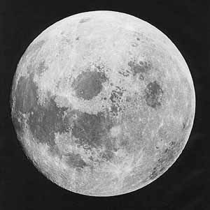
At the termination of the Apollo program in December 1972, nearly 20 percent of the surface of the Moon had been photographed in detail....
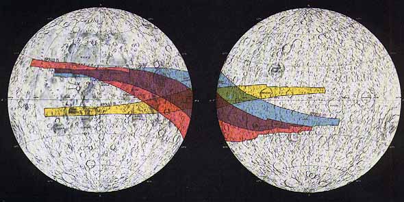
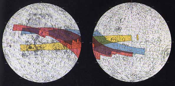
[2] FIGURE 1.-Above: Mapping camera coverage obtained by the Apollo 15, 16, and 17 missions. Only areas photographed in sunlight in the vertical mode are shown. Excluded are areas photographed obliquely, those in darkness beyond the terminator, and regional scenes taken after leaving lunar orbit. Facing page: Panoramic camera coverage obtained under the same conditions. [Base map courtesy of the National Geographic Society] [Note: For both maps: Near side is on the left and the Far side is on the right. Red: Apollo 15; Yellow: Apollo 16; Blue: Apollo 17. Chris Gamble, html editor]
...from orbit by a variety of camera systems (fig. 1). A selected sample of the nearly 18 000 orbital photographs so acquired is shown in this volume. (See app. A for an index of photographs.) The tremendous success of the Apollo photographic mission must be attributed ultimately to the great dedication, enthusiasm, and ability of the members of the Apollo program. Their efforts have resulted in a great harvest of new scientific information and a consequent increase in knowledge for mankind.
Early in the Apollo program, then directed by Lt. Gen. Sam C. Phillips, it was realized that adequate planning for the acquisition of photographs would require the participation of many individuals acting in an advisory capacity. On September 6, 1968, prior to the flight of Apollo 8, an Ad Hoc Lunar Science Working Group was convened at the Manned Spacecraft Center (now Johnson Space Center), Houston, [3] Tex. The Working Group's function was to recommend target areas of scientific interest for lunar photography. This group planned and supported the photography done on the first five lunar orbital missions (Apollos 8 and 10 through 13; Apollo 9 was an Earth orbital mission) working with the Mapping Science Branch of the Science and Applications Directorate of the Manned Spacecraft Center. Hasselblad cameras with 80- and 250-mm lenses constituted the major photographic system employed on these early flights (table 1). (App. B contains a list of lunar probes.)
On December 14, 1969, a year before Apollo 14 was launched, Dr. Rocco Petrone, Apollo Project Director, established the Apollo Orbital....
|
Camera |
| ||||||||
|---|---|---|---|---|---|---|---|---|---|
|
8 |
10 |
11 |
12 |
13 |
14 |
15 |
16 |
17 | |
|
. | |||||||||
|
Data acquisition (Maurer) |
X |
X |
X |
X |
X |
X |
X |
X |
X |
|
70-mm EL (Hasselblad) |
X |
X |
X |
X |
X |
X |
X |
X |
X |
|
70-mm DC (Hasselblad) |
X |
X |
X |
X |
X |
X |
X |
X |
X |
|
Lunar topographic (Hycon) |
. |
X |
X |
. | |||||
|
35-mm (Nikon) |
. |
X |
X |
X | |||||
|
Mapping and stellar (Fairchild) |
. |
X |
X |
X | |||||
|
Panoramic (Itek) |
. |
X |
X |
X | |||||
[4] ...Science Photographic Team because Apollo 14 was the first mission to include an orbital mapping camera. The purpose of the team was to provide "scientific guidance in the design, operation, and data utilization of photographic systems for Apollo program lunar orbital science." The team included a chairman and 12 members who were specialists in the fields of geology, geodesy, photogrammetry, astronomy, and space photographic instrumentation:
Frederick J. Doyle, Chairman (photogrammetry), U.S. Geological Survey
Lawrence Dunkelman (astronomy), NASA Goddard Space Flight Center
Farouk El-Baz (geology), Bellcomm, Inc.; later, the National Air and Space Museum, Smithsonian Institution
William Kaula (geodesy), Institute of Physics and Planetary Physics, University of California at Los Angeles
Leon J. Kosofsky (space photography), NASA Headquarters
Donald Light (photogrammetry), Defense Mapping Agency Topographic Center
Douglas D. Lloyd (space photography), Bellcomm, Inc.
Harold Masursky (geology), U.S. Geological Survey
Robert D. Mercer (astronomy), Dudley Observatory, Albany, N.Y.
Lawrence Schimerman (photogrammetry), Defense Mapping Agency, Aerospace Center
Helmut H. Schmid (geodesy), U.S. Environmental Science Services Administration
Ewen A. Whitaker (astronomy), Lunar and Planetary Laboratory, University of Arizona
As specified in the charter of the Apollo Orbital Science Photographic Team, its responsibilities included providing NASA with recommendations in the following areas:
(1) Equipment functional specifications:
(a) The team shall recommend functional requirement orbital photographic systems.
(b) The team shall provide technical advice during the procurement phase for photographic systems.
(c)The team shall be represented at photographic equipment ment reviews.
(2) Equipment use:
(a) The team shall participate in preparation of plans scientific use of the photographic systems and sup mission operations planning.
(b) The team shall participate in planning for coordinated, use of photographic systems to support other experiments.
(c) The team shall participate in planning for other experiments that will support photography.
(d) The team shall participate in operations planning photo graphic requirements to support Apollo lunar landing site selection.
[5] (3) Crew training: The team shall provide technical advice for and will support, as requested by the Manned Spacecraft Center, astronaut training related to photographic tasks.
(4) Real-time operations: The team shall support operations as requested by providing real- time scientific and technical advice to astronauts for photographic and related tasks.
(5) Data processing:
(a) The team shall provide technical advice in selection of film and film processing requirements to optimize postmission scientific analysis by photographic users.
(b) The team shall recommend major data reduction equipment and analysis procedures to assure that optimum scientific use is made of the photographic data obtained.
Analysis of the photographic data was carried out by a broad spectrum of scientists representing the following institutions: the U.S. Geological Survey, Bellcomm, Inc., the University of Arizona, Ames Research Center, and the Smithsonian Institution. H. Masursky directed and collated for publication the results of the studies relating to the scientific interpretation of the photographs. He and his colleagues, T. A. Mutch of Brown University and G. W. Colton, K. A. Howard, and C. A. Hodges of the U.S. Geological Survey, performed the same function for the last three Apollo missions. Many of the studies were performed as part of the later NASA-funded experiment S-222, which analyzed data after the completion of the flights.
In preparation for the Apollo program of landing men on the surface of the Moon, the Lunar Orbiter project inserted five spacecraft into lunar orbit. Their cameras photographed almost all of the lunar surface (Kosofsky and El-Baz, 1970; NASA Langley Research Center, 1971). However, the nature of the camera's electronic readout system was such that it was difficult to measure positions on the lunar surface accurately from the Lunar Orbiter pictures. Another disadvantage was that little stereoscopic coverage was obtained, making three-dimensional measurements impossible. Furthermore, most Lunar Orbiter pictures were taken under low Sun angles so that few high Sun pictures showing differences in albedo were available. The Apollo photographic systems succeeded in correcting these conditions.
Two groups of cameras were used for Apollo orbital photographs: those in the command module (CM) which were handheld or mounted on brackets and operated by the astronauts, and those that were stowed in the scientific instrument module (SIM) bay in the service module (SM) and remotely operated by the astronauts from the CM. Table 1 lists the photographic systems carried on these missions, and table 2 lists their characteristics.
Hasselblad cameras, using both black-and-white film and color film, were carried on all lunar orbital flights of the Apollo program. On Apollo missions 8 through 14 the bulk of the photogeologically useful pictures acquired was taken with the Hasselblad systems. Hasselblad....
|
Camera |
Features |
Film size and type |
Uses | |
|---|---|---|---|---|
|
. | ||||
|
SIM bay: |
Mapping (Fairchild) |
Electric; 76-mm focal length lens; reseau crosses, fiducial marks, time, altitude, shutter speed, and forward motion control setting recorded on each frame. |
127 mm; type 3400 Panatomic-X aerial.
|
To provide mapping quality photography (25- to 30-m resolution)-when used stereoscopically and in conjunction with auxiliary data, the geometry of the lunar surface can be reconstructed with a higher degree of precision than possible with earlier systems. |
|
Stellar (Fairchild)
|
Part of mapping camera system; 76-mm focal length lens; axis oriented at 96 to mapping camera axis; exposure synchronous with mapping camera exposures; reseau crosses, fiducial marks, time, and altitude recorded on each frame. |
35 mm; type 3401 Plus-X aerial. |
To record star field at a fixed point in space relative to mapping camera axis so that orientation of the latter can be accurately determined for each mapping camera frame. | |
|
Panoramic (Itek) |
Electric; 610-mm focal length lens; optical bar design for high-resolution and image motion compensation; frame number, fiducial marks, time, mission data, velocity/height ratio, and camera-pointing attitude recorded on each frame. |
127 mm; type EK 3414. |
To provide strips of high-resolution (about 2-m) stereoscopic coverage for relatively large- scale topographic mapping and for detailed photogeologic analysis. | |
|
. | ||||
|
CM: |
Hasselblad EL |
Electric; interchangeable 80-, 105-, 250-, and 500-mm focal length lenses; 105-mm lens transmits ultraviolet (UV) wavelengths. |
70 mm; color reversal films SO-121 and S0-368 Ektachrome MS; black and white films 3400 Panatomic X, 2485, S0-349 aerial, and 3414 aerial; spectroscopic film (W-sensitive) IIa- O.a |
To document operations and maneuvers; to obtain convergent stereoscopic coverage of candidate landing sites, particularly with the 500-mm lens; to photograph preselected orbital science targets, different terrain types near the terminator, astronomical phenomena, views of the Moon after transearth injection, views of Earth, and to acquire special UV spectral photographs of the Moon and Earth. b |
|
Hasselblad DC |
Electric; 80-mm focal length lens; reseau plate. |
70 mm; black and white films 2485, 3400 Panatomic X, and S0-349 aerial. a
|
To obtain strips of stereoscopic coverage of the approach paths to candidate landing sites, as well as of orbital science targets. b
| |
|
Lunar topographic (Hycon, later Actron) |
Vacuum platen and image-motion compensation; 457-mm focal-length, f/4 lens; fiducial marks, time, and shutter speed recorded on each frame. |
127 mm; black and white films 3400 Panatomic X and S0-349 aerial. a
|
Primarily to obtain high-resolution coverage of the Apollo 16 candidate landing site area near Descartes on the Apollo 14 mission. Camera malfunction prevented achieving this and most other goals. b
| |
|
Data acquisition (Maurer) |
Electric; interchangeable 5-, 10-, 18-, 75-, and 200-mm focal length lenses. |
16 mm; color reversal films S0-368 Ektachrome MS, SO-168 Ektachrome EF, and S0-368 Ektachrome EF; black and white films 2845, SO-164 Panatomic X, and AEI 16. a |
To document engineering and operational data, experiment records within the CSM maneuvers with the lunar module (LM), CM entry, and landmark tracking; to photograph general targets inside and outside the CSM; to obtain continuous sequence terrain photography. b
| |
|
|
35-mm (Nikon) |
Mechanical; through-the-lens viewing and metering; 55-mm focal length lens. |
35 mm; black and white film type 2485; SO-168 Ektachrome EF.a |
To photograph, under dim light conditions, astronomical phenomena and lunar targets illuminated by Earth shine.b |
[8] FIGURE 2 [above] .-Arrangement of the equipment used for the orbital experiments conducted from the SIM bay during Apollos 15 and 16 is shown. A largely different assortment of instruments was carried on Apollo 17. The extravehicular activity (EVA) foot restraint is used by the astronaut who retrieves the exposed film from the cameras during the return of the spacecraft to Earth.
....photographs were used to study future landing sites, to perform geologic mapping, to conduct geodetic studies, to study the regional and local geology of the Moon, and to train astronauts for later lunar missions.
On Apollo missions 13 and 14, a lunar topographic camera (the Hycon camera) was carried in the CM. A very limited amount of photography was obtained with it, however, because the Apollo 13 mission was aborted before tile photographic phase was to have begun and on Apollo 14 the camera malfunctioned early in lunar orbit, just as the spacecraft approached the Apollo 16 candidate landing site in the Descartes region. The necessary photographs of the Descartes area were obtained with the Hasselblad (500-mm lens) camera by pitching the spacecraft to compensate for its forward motion in orbit so that no image smear appeared on the photographs.
On Apollos 15 to 17 the much-more-sophisticated mapping and panoramic camera systems were used. These, and other remote sensing instruments, were mounted in the SIM bay that was added to the CSM for the last three missions (fig. 2). Higher resolution and much more systematic coverage of the ground track areas traversed by the spacecraft were obtained with these cameras. Personnel from the Flight Operations Directorate, Johnson Space Center, monitored the performance of the instruments and were essential to the successful acquisition of the data.
The mapping camera system consisted of a terrain camera coupled to a stellar camera and a laser altimeter. Each exposure of the terrain camera was accompanied by a stellar camera exposure of the star field to provide a means of determining the orientation of the spacecraft in space. Simultaneously the laser altimeter recorded the height of the [9] spacecraft above the Moon's surface. At nominal orbital altitude the terrain camera was capable of resolving objects on the surface as small as 25 to 30 m on a side. The geometry of the optical system of the terrain camera permitted the metric pictures to be used for precise triangulation and cartography. Thus they can be used for three purposes: (1) to construct a geodetic network of control points for topographic mapping with both terrain and panoramic camera photographs, (2) to compile medium-scale topographic maps, and (3) to perform photogeologic interpretation.
The panoramic camera, capable of attaining l-m resolution on the surface from orbital altitude, provided high-resolution stereoscopic photographs of the surface during periods of varying Sun angle conditions. High Sun angle pictures show differences in albedo to advantage, and low Sun angle pictures delineate small and low relief features more clearly.
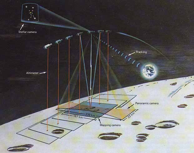
The coordinated operation of the three components of the mapping camera system is illustrated schematically in figure 3. Except when in use, the mapping camera system is in a retracted position in the SIM bay. During photographic sequences the system is extended on rails to a point where the terrain and stellar cameras have clear fields of view. The components of the system are illustrated in different degrees of detail in figures 4 through 6. The terrain camera component has a 76-mm, f/4.5 lens to cover a square frame 114 mm on a side. The shutter consists of a pair of continuously rotating disks and a capping blade. An automatic exposure device selects the correct disk speed to provide a range of exposures from I /15 to 1/240 s in duration. The film is held precisely in place by pressure against a movable glass stage plate that contains reseau marks. Fiducial marks are flashed on the film marking the optical axis at midexposure time. Simultaneously, the time of exposure, to the nearest millisecond, according to the spacecraft clock is recorded on the data block on each frame. The film magazine holds 460 m of 127-mm film-enough for 3600 frames. The terrain camera was designed to compensate for the image blur that would otherwise be present in a picture taken from a rapidly moving camera; the stage plate that controls the exposure is driven forward in the direction of flight at a velocity proportional to the ground speed of the spacecraft. The velocity over height value (v/h) is set by the astronaut from the CM. Successive frames overlap by 78 percent (fig. 3) and alternate frames by 57 percent; thus each point on the lunar surface appears on at least four successive frames. In most cases successive orbital passes provided for 60 percent sidelap.
The stellar camera exposes 35-mm film with a 76-mm f/2.8 lens. Each exposure, of 1.5-s duration, is made simultaneously with an exposure of the terrain camera. In the stellar camera the film is pressed against a glass stage plate that bears an array of 25 reseau crosses. The....
|
[10] |
 |
|
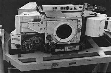
[11] FIGURE 4 [right].- The Apollo mapping camera system, which consists of a terrain or mapping camera, a stellar camera, and a laser altimeter. The three components can be located by referring to figure 5. [Photograph courtesy of the Fairchild Camera and Instrument Corporation] |
 |
|
| |
|
FIGURE 5 [right].- A schematic drawing showing the major components and selected parts of the mapping camera system. The angular fields of view (FOV) are given in degrees for the stellar and mapping (or terrain) camera components.
|
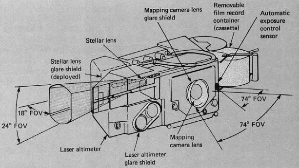 |
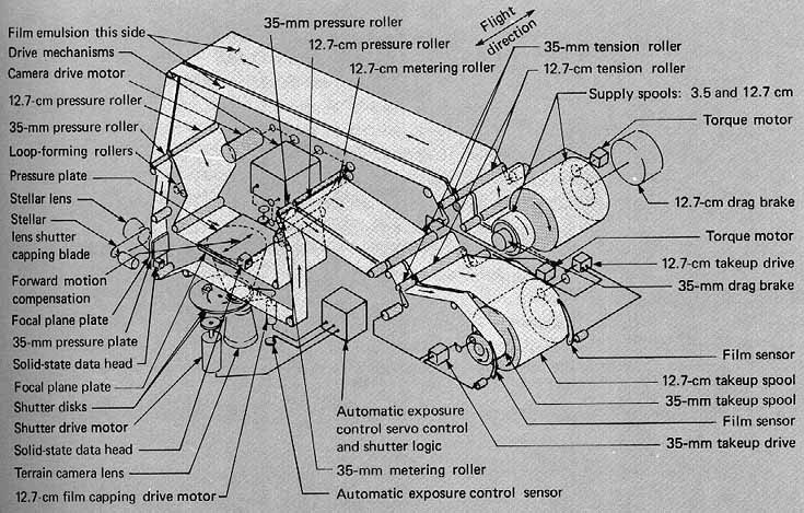
[12] ....film is 155.4 m long, allowing 3600 exposures to be made. The stellar camera is rigidly mounted with its optical axis at an angle of 96° to that of the terrain camera. Thus the orientation of the latter (as well as of the spacecraft) can be determined from the known position of the stars recorded by the stellar camera.
The laser altimeter is alined parallel to the optical axis of the terrain camera. A ruby laser emits a very short pulse of red light at the time of each mapping camera exposure and a photomultiplier tube detects the portion of the pulse that is reflected from the Moon. Measurement of the round trip traveltime of the pulse multiplied by one-half the speed of light gives the precise altitude of the spacecraft above the Moon's surface. With the orientation and altitude of each metric photograph thus determined, the metric photographs can be tied together to create a geodetic network of control points.
The Panoramic Camera
High-resolution stereoscopic coverage of large areas of the lunar surface was provided by the panoramic camera. The camera used on the Apollo missions, a modified version of the U.S. Air Force's KA-80A "optical bar" camera, was manufactured by Itek Corp.
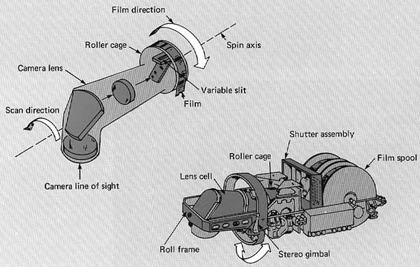
Figure 7 [above].- The panoramic camera shown diagrammatically. Left: The optical bar concept. Right: The camera mechanism with covers removed.
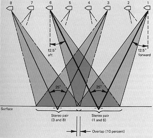
The panoramic camera mechanism allowed an exceptionally wide area to be covered with a narrow-angle lens. This is accomplished by [13] rotating the lens during the exposure. The 610-mm f/3.5 lens has eight lens elements and two folding mirrors. The optical bar, consisting of this optical system, an exposing slit, and a roller cage that supports the film, rotates continuously during camera operation. Film exposure starts at 54° on one side of the flight line and extends to 54° on the other side for a total scan of 108° perpendicular to the flight path. In the direction of flight, the field of view is 10.6°. The photographic exposure of the film is determined by the rate of rotation of the optical bar and the width of the slit. To prevent image smear due to the rotation of the lens, the film is pulled across the slit in the opposite direction.
The optical bar and the motor that spins it are mounted in a roll frame that is connected to the camera's main frame by a gimbal structure (fig. 7). By rocking the roll frame about this gimbal, the camera provides both stereoscopic overlap and forward motion compensation. The exposures are made with the roll frame rocked alternately 12.5° forward and 12.5° aft (fig. 8). The camera cycle rate is controlled so that the ground covered by a forward-looking photograph is covered again five frames later by an aft-looking photograph, thus providing a stereo pair. During the time (about 2 s) that each of these exposures is being made, the same gimbal mechanism "freezes" the ground image by matching the rocking motion to the angular rate at which the ground passes beneath the spacecraft. The camera's v/h sensor, which measures this rate continuously, is the pacemaker for the entire operation.
[14] The main frame of the camera holds all film handling mechanisms. The panoramic camera must move considerable lengths of film rapidly. During the 2s it takes for one exposure, 1.2 m of film must be pulled smoothly over the roller cage and across the exposure slit. This action is...
...repeated every 6 s. A load of film sufficient for 1600 exposures is 2 km long and weighs 25 kg. Because the forces that would be required to start and stop such a mass of film intermittently are prohibitively large, the supply and takeup spools actually rotate continuously during camera operation. An ingenious "shuttle assembly" functions as a buffer between the continuous and the intermittent film movements. In the interval between exposures, the supply side of the shuttle accumulates enough film for the next frame while the takeup spool empties the takeup side of the shuttle.
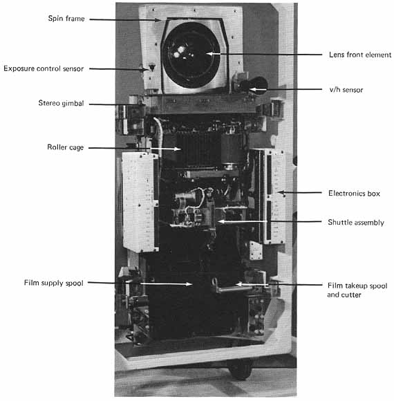
The arrangement of the camera parts can best be studied in the accompanying photograph (fig. 9), which shows the camera as it would be seen from outside the SIM bay if the light-excluding covers were removed A more detailed description of the camera systems is given in Kosofsky (1973).
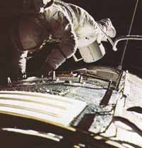
The film cassettes from both the metric and panoramic cameras were recovered by the command module pilot (CMP) on the way back to Earth (fig. 10) and stored in the CM for later processing at the Photographic Technology Laboratory, Johnson Space Center.
Personnel from the Science and Applications Directorate and the Apollo Spacecraft Programs Office were responsible for designing the mission plans. The final plans incorporated many of the recommendations made by the Apollo Orbital Science Photographic Team.
Metric camera photography for Apollo 15 had several limiting constraints set by the instrumentation, the requirements of other SIM bay experiments, and the orbital plane of the CM. The high inclination o] the Apollo 15 orbital plane (approximately 25° from the equator; sec fig. 1) resulted in a relatively wide separation of the ground tracks of succeeding revolutions. Because 60 percent side overlap was required for pictures taken in adjacent orbits, careful planning and budgeting of the film was required.
The performance of other scientific experiments using instruments in the SIM bay prohibited concurrent use of the metric camera during some parts of the mission. Some of the experiments were conducted with the SIM bay pointed away from the Moon. During most of the time devoted to the geochemical experiments, such as the gamma ray spectrometer experiment, the SIM bay was pointed toward the lunar surface but the metric camera was retracted and the lens was covered to prevent radioactive thorium contained in the camera and laser altimeter lenses from interfering with the spectrometric measurements. During one orbit, as a test, the two instruments were run concurrently. Radiation from the lenses was less than anticipated; consequently, during the Apollo 16 mission, the two instruments were run concurrently, with only slight degradation of the spectrometric measurements.
Despite constraints such as these, all objectives of the Apollo 15 photographic plan were met, and an excellent set of vertical metric photographs was acquired. In addition, many oblique photographs looking 40° fore and aft and to the north and south of the ground tracks were obtained; although they are of limited use in making topographic maps, they are extremely useful in photogeologic studies.
The panoramic camera on Apollo 15 obtained excellent, very useful photographs, even though its operation was subject to constraints similar to those placed on the mapping camera system. Furthermore, the panoramic camera could only be run for about one-half hour (half the sunlit portion) of any given orbit because of thermal limitations on the instruments. The area of coverage was limited to the same area covered by the mapping camera system because only the latter could provide the geodetic control necessary for constructing mosaics and orthophoto maps from the panoramic camera pictures.
On the Apollo 16 mission, film budgeting was not difficult because the low angle of the orbital plane (about 9° from the equatorial plane) restricted the spacecraft to a narrow orbit belt and hence limited the width of the area that could be photographed from the vertical mode (fig. 1). The planned coverage for both systems was obtained long before the film loads were consumed. The original mission plans were to take the metric and panoramic photographs very early and very late in the orbital phase when the near-side terminator had progressed far [17] enough west to permit photographing the western limb. However, early in the orbital phase problems developed with the spacecraft orientation mechanism that forced a decision to shorten the mission time by 1 day. Although the time available for orbital photography was less than originally planned, about 90 percent of the planned photographic coverage was obtained. Only the westernmost part of the orbital tracks was not photographed.
The orbital attitude of the Apollo 17 spacecraft was similar (about 20° from the equatorial plane) to that of Apollo 15; because much of the ground track area had previously been photographed by the earlier mission (fig. 1), the 60 percent overlap requirement was waived. In some areas previously photographed during the Apollo 15 mission, photographs were obtained when the Sun angle was different from that of the earlier photographs; additional information was supplied in this way.
Apollo 17 carried several new orbital experiments including the infrared scanning radiometer, the UV spectrometer, and the lunar sounder experiments. Some of these required special spacecraft attitudes and freedom from interference, thereby reducing the amount of time available for using the SIM bay camera systems. However, modifications made in the photographic plan to accommodate these experiments on this and earlier missions proved worthwhile because the results of the experiments have proved useful in supporting photogeologic interpretations.
The panoramic camera was used to extend the Apollo 15 photographic coverage and to fill gaps in both the Apollo 15 and 16 belts.
When the Apollo program ended with the successful completion of mission 17, nearly 10 000 metric and 4800 panoramic photographs had been acquired. Controlled orthophotomaps at a scale of 1:250 000 (fig. 11) are being made from the metric photos; the panoramic camera photographs are being used to make large-scale maps at 1:50 000 and 1:10 000 scale for particular areas of scientific interest (fig. 12). The basic data analysis scheme for converting the raw photographs into finished map products is described in Appendix C (Doyle, 1972). The production of these maps is a massive undertaking and will take many years to complete.
Copies of individual Apollo photographs may be ordered from-
- National Space Science Data Center
- Goddard Space Flight Center
- Greenbelt, Md. 20771
- Goddard Space Flight Center
Orthophotomaps and other cartographic products may be obtained from-
- Lunar and Planetary Programs Office
- National Aeronautics and Space Administration
- Washington, D.C. 20546
- National Aeronautics and Space Administration
|
|
|
|
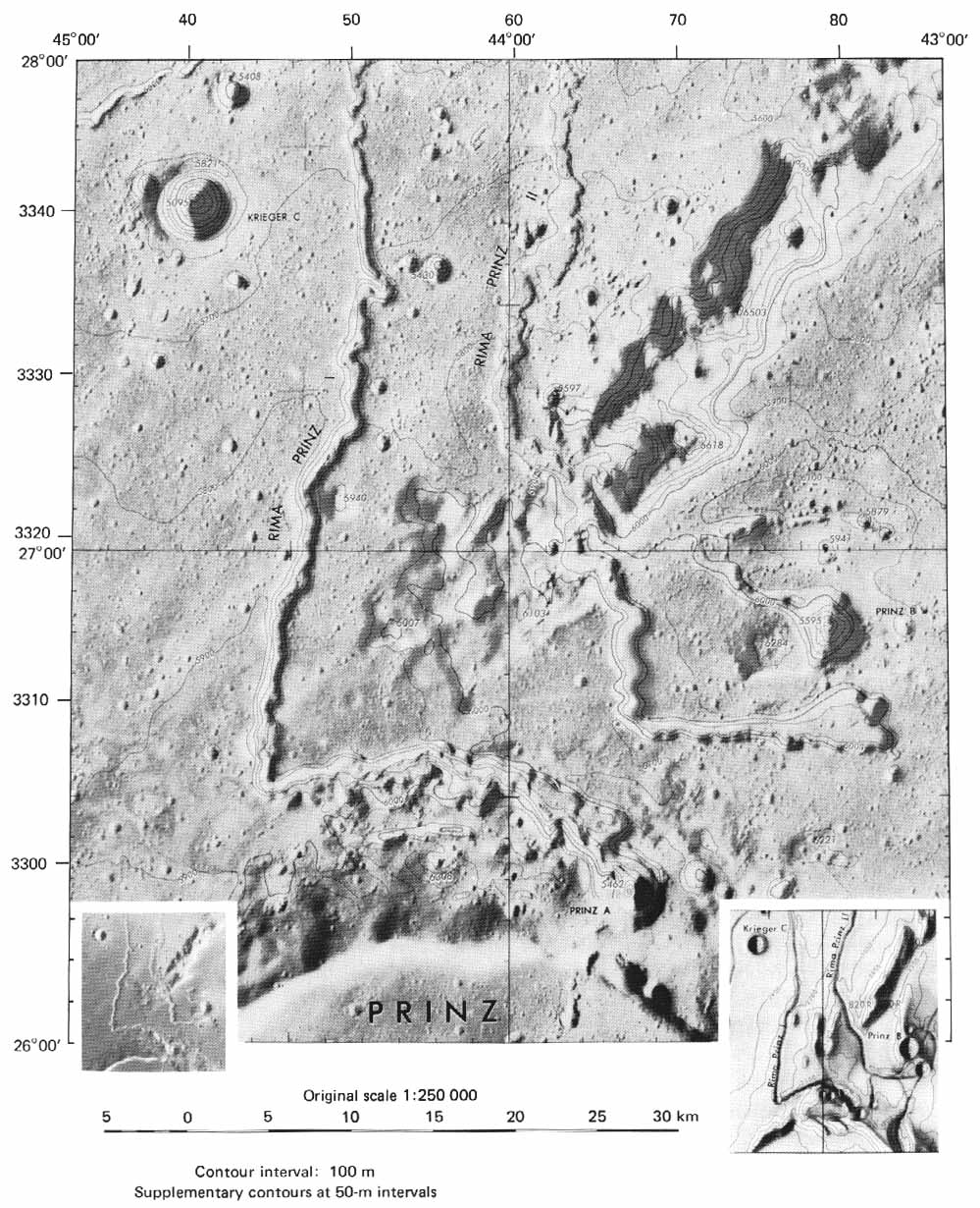
[19] FIGURE 11 [above].- An example of the detailed topographic portrayal made possible by mapping camera photographs. The sample area shown is part (about one-fifth) of Lunar Orthophoto Map sheet LTO39A3(250), prepared by the Defense Mapping Agency Topographic Center, Washington, D.C., and published in 1973. The rilles are Rima Prinz I and II in northern Oceanus Procellarum. Topographic contour lines (lines of equal elevation) in red are superposed on an orthophotograph version of mapping camera frame AS15-2474 enlarged to the scale of the map. For comparison (or contrast) that portion of the frame corresponding in area to the sample map is shown in the lower left corner. At the lower right is the same area as it appeared on Lunar Aeronautical Chart (LAC) 39, which was one sheet of the earliest series of detailed cartographic maps of the Moon showing surface relief. Compiled entirely from photographs taken through Earth-based telescopes and from direct telescopic observations, it was published in 1963 by the U.S. Air Force Aeronautical Chart and Information Center, St. Louis, Mo.-G.W.C.
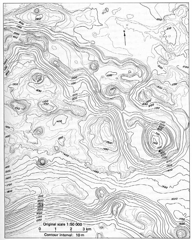
FIGURE 12 [above] .-Another example of the versatility of photographs taken of the lunar surface from orbital altitudes. This topographic contour map was compiled by photogrammetric methods from two Apollo 15 panoramic camera frames. It shows a small area around the head of Rima Prinz I, one of the rilles covered in the preceding map (fig. 11). It was prepared in Flagstaff, Ariz., in support of a geologic study of rilles and their origin. It will not be published separately, hence, many of the stylistics of a map prepared for publication are lacking. Nevertheless, it is a fine example of what can be "seen" in panoramic camera pictures taken, in this case, at an altitude of 119 km.-G.W.C.
[20] In this section we discuss only those orbital experiments that collected data relevant to photointerpretation. All of the instruments used for these experiments were transported in the SIM bay.
The gamma ray spectrometer (GRS) experiment aboard Apollos 15 to 16 detected gamma rays produced by the radioactive decay of materials on the lunar surface; areal variations in the intensity of gamma radiation make it possible to map the distribution of rock types along the ground tracks. The detector, which was mounted on a boom, contains a crystal that responds to an incident gamma ray by emitting a pulse of light. The light-pulse is converted by a photomultiplier tube into an electrical signal the strength of which is proportional to the energy of the gamma ray. The electrical signal is then processed and sent to Earth over the radio telemetry channel. Signals from other charged particles are canceled in the electronics processing so that only the gamma rays signals are returned to Earth.
The X-ray fluorescence (XFE) experiment was used on Apollo missions 15 and 16 to measure the chemical composition of the Moon. The sunlit portion of the Moon is constantly bombarded by solar X-rays. It is the secondary fluorescent X-rays emitted from the lunar surface material that are detected and measured by this experiment. In particular, the characteristic wavelengths and energies of magnesium, aluminum, and silicon were detected. Variation of the ratios of Mg/Si and Al/Si are extremely useful for determining the chemical composition and hence the type of rock constituting the surface materials.
The bistatic radar experiment, conducted on Apollo missions 13 through 16, measured the electromagnetic and structural properties of the outer few meters of the Moon's crust. Radio signals emitted from the CSM were reflected from the Moon and recorded by radiotelescopes on Earth. As the CSM orbited, the impinging beam of radiowaves, which covered a 10-km-square area of the surface, scanned the lunar disk. The characteristics of the areas so measured were then interpreted in terms of dielectric properties, size of the fragments composing the surface debris, and the magnitude and frequency of sloping surface. The experiment thus provides a means of measuring the small-scale "roughness" of the lunar surface.
The particles and fields subsatellite magnetometer experiment was conducted during Apollos 15 and 16. Instrumentation consisted primarily of a magnetometer mounted on a subsatellite transported in the CSM SIM bay. The subsatellite was inserted into lunar orbit shortly before the CSM began its return to Earth. The purpose of the magnetometer was to record variations in time and space of the magnetic field at Apollo orbital altitudes. The resulting data are being used to complement data obtained by the magnetometers placed on the surface of the Moon and the magnetometer carried onboard the much higher orbiting Explorer 35.
The S-band transponder (SBT) experiment was conducted on the last three missions, and gravity field observations were made on all missions.
[21] The transponder was used to measure areal variations in the Moon's near-side gravitational field by recording very slight changes in the velocity of the orbiting CSM, subsatellite, and the LM. Changes in the gravitational field are caused by differences in density of the rocks. The experiment thus provides data for mapping the density of the rocks composing the upper part of the lunar crust. Radio signals transmitted to the three orbiting spacecraft components from Earth were multiplied by a constant (for electronic reasons) and then retransmitted to Earth. The difference in frequency between the transmitted and returned signals is a function of the velocity of the spacecraft.
The Apollo lunar sounder (ALSE) experiment was conducted only on Apollo 17. It used radar techniques to "see" into the Moon to depths as great as 1 1/2 km. The sounder was designed for three primary modes of operation: the sounding mode detected and mapped subsurface features, and the profiling and imaging modes provided quantitative metric and topographic data as well as albedo measurements. Three frequencies of radiowaves were transmitted to the Moon from antennas mounted on the SM. Some of the waves were reflected by the lunar surface while others penetrated to various depths depending upon the type of material encountered. Those that penetrated the Moon were reflected by layers of rock within the Moon. The reflected component of the radiowaves was detected by the spacecraft antennas, delivered to the receiver, amplified and converted to light signals, and recorded optically on photographic film. The character of the reflected waves furnishes information about the nature of subsurface layers, and their return times tell the depth of the reflecting layers.
The infrared scanning radiometer (ISR) on board Apollo 17 was used to measure the emission of heat from the Moon's surface. A sensitive thermometer was mounted at the focus of a telescope. Light from a small area (about 2 km2 ) of the Moon's surface enters the telescope through a mirror that oscillates back and forth to scan the surface of the ground track. After passing through various components of the instrument to a detector, the radiant energy of the light beam is changed into an electrical signal. This electrical signal is related to the temperature of the spot that is viewed by the telescope at any instant in time. The thermal properties so measured can then be correlated with known geographic and geologic features.
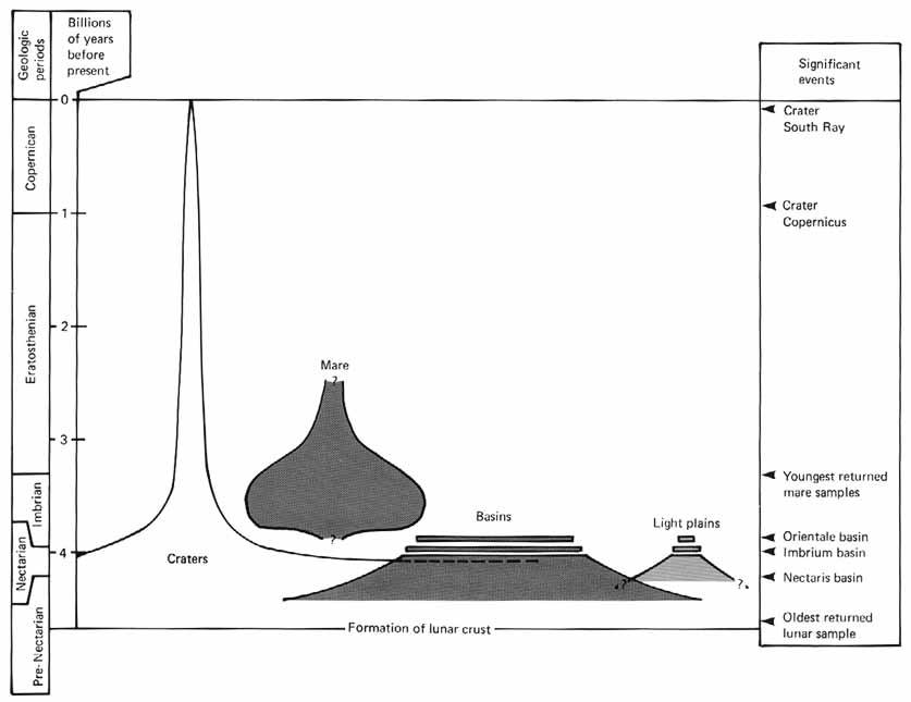
Interpretation of the photographic products of the Apollo missions, augmented by the array of data obtained from the geochemical and other orbital experiments, has given rise to many new ideas about the configuration and origin of the lunar crust. The evolution of the Moon's crust is diagramed in figure 13 to show the temporal relationship of the major processes that affected the upper part of the crust.
One of the notable returns from the Apollo program is the radiometric dating of returned samples showing their great antiquity. This information is proof that the lunar surface we see is very old-...
[23]...much older than the surface of Earth, which has been so degraded and changed by dynamic forces that primary crustal material is now largely unrecognizable. The lunar samples, therefore, provide a clue to the possible composition of original rocks on Earth. Information from the returned samples can also be extrapolated to date rocks underlying the lunar surface far from the landing site areas. In this way a new understanding of the general history of the Moon is emerging.
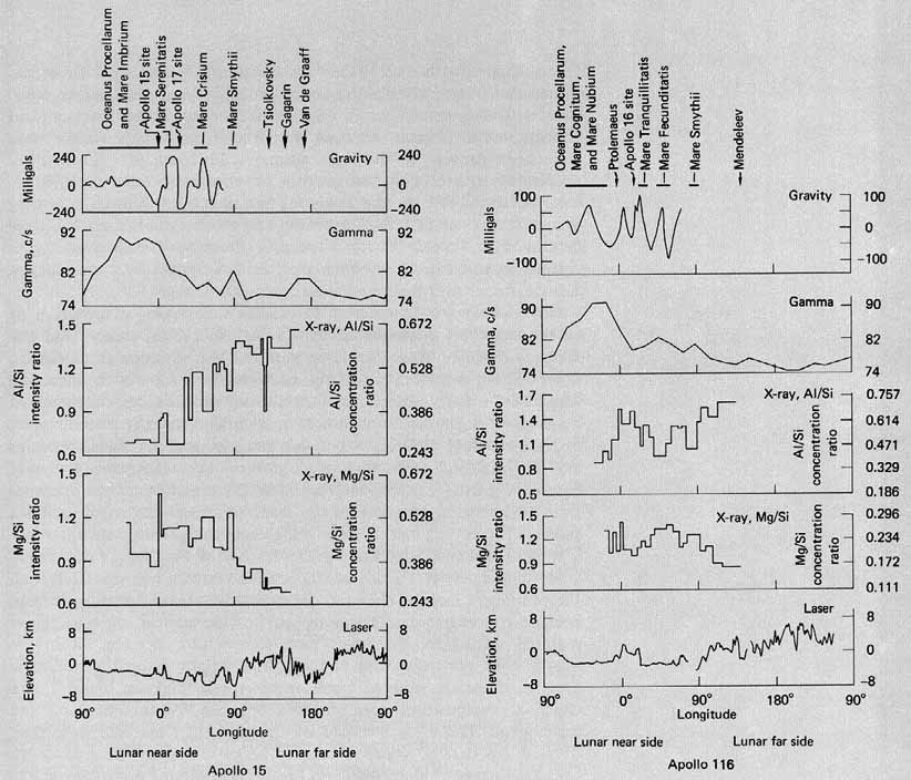
The mare areas of the near side of the Moon appear to be 2 to 5 km below mean lunar radius; the far side appears to be as much as 5 km above mean radius. Basaltic lava flows (the "maria") fill most of the low-lying basins on the near side (fig. 14); thicker, low density rocks underlie the high-standing ("terra") regions found on both near and far sides. The marked difference between the dark lowland regions (maria) and the bright highland regions (terrae) was first noted by Galileo in 1609. The results from several of the Apollo orbital experiments have confirmed their essential difference (fig. 15). Laser altimetry and gravity tracking results have defined marked differences in elevation. Variations in Al/Si and Mg/Si ratios obtained from the X-ray fluorescence experiment have confirmed the chemical difference between the two terrain types and strongly indicate that there has been little lateral surface transport of material from the highlands to the low-lying mare basins (Adler et al., 1974). Variations in gamma activity determined by gamma ray spectrometry have also documented this essential difference.
Recent estimates of the thickness of the lunar crust based on orbital laser altimetry, S-band tracking data, and surface seismic information indicate the existence of 20 km of basalt overlying 20 km of anorthositic material-crust-under eastern Oceanus Procellarum, 5 km of crust under some of the circular mare basins, 48 km under the near-side highlands, and 74 km of crust under the far-side highlands (Kaula et al., 1974). Variation in thickness of the lunar crust may have been caused by early chemical differentiation of the crust soon after the Moon was locked to Earth by gravitational attraction.
Orbital and surface magnetometer measurements (Coleman et al., 1972a,b,c) correlate closely with the gamma ray highs and lows. The deflection of the solar wind observed over some limb areas by the subsatellite magnetometer are thought to be caused by regions of high magnetization in that part of the Moon.
Tracking of the spacecraft as they respond to gravity has shown that craters up to 100 km in diameter are deficient in mass; that is, they constitute gravity lows. On the near side, mare- filled craters more than 150 km in diameter have positive gravity anomalies (Sjogren, Wimberly, and Wollenhaupt, 1974). The anomalies are probably caused by the dense basaltic lava flows that fill the craters and the underlying denser materials in the lower part of the crust that were thrust upward by the impact.
Basaltic lava flows occupy irregular mare areas, such as the very large one recognized as Oceanus Procellarum, as well as the many circular multiringed structures 150 km or more in diameter that are thought to have originated as impact basins (fig. 14). Among the best examples of...
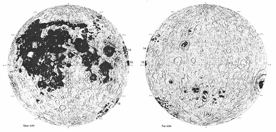
- [24] FIGURE 14 [above].- This highly simplified geologic map distinguishes between the two major types of lunar terrain. Mare areas are shown in black, and terra or highland areas are shown without overprint as they appear on "The Earth's Moon" [courtesy of the National Geographic Society]. The unequal distribution of mare materials is shown to advantage on this equal area projection. Also clearly evident is the tendency of mare materials to be concentrated within the margins of large multiringed circular basins. The Serenitatis (7), Crisium (12), Moscoviense (17), Ingenii (18), and Orientale (19) Maria are especially good examples. The broad irregular expanse of mare material known as Oceanus Procellarum is another type of occurrence.- G.W.C.
- Legend:
- 1 Oceanus Procellarum
- 2 Mare Imbrium
- 3 Mare Cognitum
- 4 Mare Humorum
- 5 Mare Nubium
- 6 Mare Frigoris
- 7 Mare Serenitatis
- 8 Mare Vaporum
- 9 Mare Tranquillitatis
- 10 Mare Nectaris
- 11 Mare Humboldtianum
- 12 Mare Crisium
- 13 Mare Fecunditatis
- 14 Mare Marginis
- 15 Mare Smythii
- 16 Mare Australe
- 17 Mare Moscoviense
- 18 Mare Ingenii
- 19 Mare Orientale
- 1 Oceanus Procellarum
[26]...impact basins with mare filling are Imbrium, Crisium, and Orientale. Other multiringed circular basins of probable impact origin are, however, devoid or nearly devoid of mare fill. Structural, geochemical, and topographic differences between the circular and irregular mare areas have been proven by the laser altimeter, lunar sounder, gamma ray spectrometer, and X- ray fluorescence experiments, as well as by photointerpretation. The circular maria are bounded by striking cliff-forming arcuate segments of crustal blocks while the irregular maria have low serrate edges. Positive gravity anomalies ("mascons") delineated by the S-band transponder experiment are associated with the impact basins but are absent over the irregular areas.
There are many hypotheses to explain the varying distribution of crustal materials documented by the Apollo orbital sensors and the samples returned from the lunar surface. The variation in thickness, composition, and elevation of the mare and terra regions, the increased gamma ray activity observed in the midfront and far sides, the increased magnetic and gamma ray measurements obtained over some limb areas, and the essential differences between irregular and circular mare basins and the highland areas all imply a controlling mechanism. A theory based on mantle convection (the internal circulation of hot material) gives a possible explanation for the observed sensor data and describes a possible controlling mechanism for the chemical, geophysical, and topographic variations. Very early in tile history of the Moon's formation, when it was very hot and fluid, the mantle material was separated from the primordial melt by chemical differentiation. Lower density material became concentrated in the upper part of the mantle, whereas denser material settled in the lower part. Convection currents within the mantle then partially stripped the lighter weight material from' some areas to cause the marked variation in crustal thickness, density, and chemical composition now observed between the present terra and mare areas. The areas stripped of lighter weight material were then flooded by basalts, which presently lie on a greatly thinned crust. Localized areas of increased concentrations in gamma ray and magnetic activity were caused by internal circulation and concentration of materials with higher magnetic and gamma ray properties. The mantle convection theory, however, is still being debated. True understanding of the development of the lunar crust may require years of additional study.
The mechanics of impact cratering have been studied intensively with the aid of the Apollo data. Craters ranging in size from the giant basins hundreds of kilometers across (like the Imbrium basin), to the smallest craters visible in orbital photographs (1 m in diameter), to microcraters on the surface of minute glass spheres contained in the returned lunar soil samples have been studied.
Crater ejecta material has been studied and classified into two groups: ballistic ejecta that is thrown out to form linear or curved patterns of rays and clusters of secondary craters on the Moon's surface, and fine-grained fluidized ejecta that locally blankets the lunar surface and forms patterned flows extending downrange from the primary [27] impact crater. The continuous ejecta blanket is apparently emplaced by base surge flow on the surface surrounding the crater. A striking example of surface patterns created by ejecta flow and its interaction with the local topography is found near the far-side crater King (fig. 159).
The continued bombardment of the lunar surface by meteoroids and secondary impact material has formed a regolith on the surface composed of breccia fragments and unconsolidated fragmental debris. The thickness and age of the regolith vary systematically. In general, thickness estimates based on crater shape agree well with estimates based on bistatic radar measurements.
A variety of features has been investigated and recognized as being of volcanic origin. Other terrain features have been more equivocally classified as possibly volcanic in origin. A succession of lava flows has been mapped in the Imbrium basin. Dark halo craters have been studied extensively and divided into two classes: The round, smooth-sided craters with no visible blocks in the crater walls are believed to be volcanic, and the dark halo material is thought to be composed of very fine-grained volcanic ejecta. Dark halo craters having irregular outlines may be impact craters from which darker material was exhumed at the time of impact. Lines or chains of craters have also been classified into two groups: volcanic crater chains (Hyginus Rille and Davy crater chain) and secondary impact crater chains extending radially from large craters (such as Copernicus, Kepler, and Aristarchus) and formed by ballistic ejecta from the large craters.
This volume was prepared under NASA contract number W-13,130. G. E. Esenwein of NASA Headquarters provided much of the initial encouragement and support needed to begin this effort. L. J. Kosofsky of NASA Headquarters also contributed materially to the completion of the volume. In addition to preparing many of the captions, Don E. Wilhelms and Keith A. Howard of the U.S. Geological Survey and Farouk El-Baz of the Smithsonian Institution participated in the preliminary selection of the photographs. Other U.S. Geological Survey members who contributed significantly to the preparation of this volume are S. S. C. Wu, photogrammetrist; J. S. VanDivier, cartographer-illustrator; and K. A. Zeller, photographer. Captions of the photographs were composed by individual authors who are identified by their initials:
G.W.C
- George W. Colton
- U.S. Geological Survey
- Flagstaff, Ariz.
- U.S. Geological Survey
R.E.E.
- Richard E. Eggleton
- U.S. Geological Survey
- Flagstaff, Ariz.
- U.S. Geological Survey
[28] F.E.-B.
- Farouk El-Baz
- National Air and Space Museum
- Smithsonian Institution
- Washington, D.C.
- National Air and Space Museum
M.J.G.
- Maurice J. Grolier
- U.S. Geological Survey
- Reston, Va.
- U.S. Geological Survey
J.W.H.
- James W. Head III
- Department of Geological Sciences
- Brown University
- Providence, R.I.
- Department of Geological Sciences
C.A.H.
- Carroll Ann Hodges
- U.S. Geological Survey
- Menlo Park, Calif.
- U.S. Geological Survey
K.A.H.
- Keith A. Howard
- U.S. Geological Survey
- Menlo Park, Calif.
- U.S. Geological Survey
L.J.K
- Leon J. Kosofsky
- National Aeronautics and Space Administration
- Washington, D.C.
- National Aeronautics and Space Administration
B.K.L.
- Baerbel K. Lucchitta
- U.S. Geological Survey
- Flagstaff, Ariz.
- U.S. Geological Survey
M.C.M.
- Michael C. McEwen
- National Aeronautics and Space Administration
- Johnson Space Center
- Houston, Tex.
- National Aeronautics and Space Administration
H.M.
- Harold Masursky
- U.S. Geological Survey
- Flagstaff, Ariz.
- U.S. Geological Survey
H.J.M.
- Henry J. Moore
- U.S. Geological Survey
- Menlo Park, Calif.
- U.S. Geological Survey
G.G.S.
- Gerald G. Schaber
- U.S. Geological Survey
- Flagstaff, Ariz.
- U.S. Geological Survey
D.H.S.
- David H. Scott
- U.S. Geological Survey
- Flagstaff, Ariz.
- U.S. Geological Survey
L.A.S.
- Laurence A. Soderblom
- U.S. Geological Survey
- Flagstaff, Ariz.
- U.S. Geological Survey
M.W.
- Mareta West
- U.S. Geological Survey
- Reston, Va.
- U.S. Geological Survey
[29] D.E.W.
- Don E. Wilhems
- U.S. Geological Survey
- Menlo Park, Calif.
- U.S. Geological Survey
- George W. Colton
Desiree Stuart-Alexander acted as contract manager for NASA. George W. Colton and Mary E. Strobell of the U.S. Geological Survey compiled the overlays and edited by the many preliminary versions of the book. Julienne M. Goodrich and Mary Nelson Rakow of the Smithsonian Institution also assisted in the many editorial tasks.
Our thanks go to all the people associated with the Apollo missions; their hard work and technical expertise resulted in the acquisition of the data that made this volume possible.
| Next |