Saturn I-IB Computer Complex
The development of the RCA 110 hardware for Saturn I tests proceeded at Huntsville under the direction of the Astrionics Laboratory with the collaboration of the electrical network group. Richard Jenke's automation team at KSC furnished operational requirements and participated in a number of design decisions. Some agreements between developer and future user came slowly. The two groups discussed the matter of control panel switches for months; the uncertainty centered on the desired status of the various test devices when the operations switched from a computer program to manual control. Eventually the two groups decided to treat each test device separately and modify the RCA 110 programs when experience dictated a change. About the same time the automation group approved a three-position switch for the Saturn IB control panel. During IB operations all signals, manual as well as automatic, would process through the computer. In the three-position switch, OFF manually terminated a function, such as opening a valve; ON manually initiated a function; and AUTO placed the computer in control for automatic testing. Experience with SA-5 demonstrated the need to prevent the computer from sending any command signals while it monitored the operation. The automation group added a discrete inhibit switch on SA-6 for the remaining Saturn I launches.7
The Cape played a larger role in the development of computer programs, called software. Marshall recognized the launch team's need to prepare its own tests and allowed KSC to manipulate "Boss," the 110's executive control program. Jenke's group, assisted by RCA, IBM, and Chrysler personnel, combined the 20 manual routines of the guidance computer checkout into four test sequences. While the performance of the RCA 110 on SA-5 left a few skeptics unconvinced, launch officials labeled the computer a success. On the following launch (SA-6) Jenke added a test sequence for automatic azimuth laying. The launch team added a cathode ray tube console (a television screen that displayed alpha-numeric characters received from the computer) for SA-7. The RCA 110 increased its monitoring role during the last three Saturn I launches, the Pegasus series.8
During the Saturn I program, automation moved forward at a slow, deliberate pace; at any time the launch team could have reverted to a manual operation. By the time of the first Saturn IB launch in February 1966, however, KSC was firmly committed to automated testing. While a completely automated checkout was still a long way off, the RCA 110A computer (a 110 with increased memory) was "on line" for the first IB operation. All test transmissions then went through the computer; if it failed, the entire checkout would stop. On-line status represented the decision to use the Saturn IB missions as a testbed for Saturn V automation.

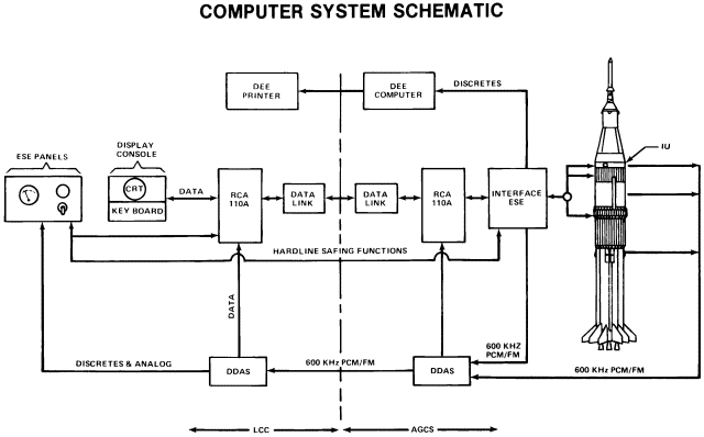
LC-34/37 computer system schematic. From B. E. Duran, "Saturn I/IB Launch Vehicle Operational Status and Experience," pamphlet 680739, Aeronautic and Space Engineering and Manufacturing Convention, Los Angeles, 7-11 October 1968. Courtesy of the Society of Automotive Engineers, Warrendale, PA.
Two RCA 110As - a "master" computer in the LC-34 blockhouse and a "slave" computer in the automatic ground control station-provided the brains for the Saturn checkout system. A high-speed data link, a coaxial cable running through the LC-34 cableway, connected the two computers. Engineers could initiate launch vehicle tests from display consoles or from programs stored within the master RCA 110A. In either case the computer in the launch control center digitized commands for transmission to the ground control station. The slave computer, housed beneath the umbilical tower, interfaced with the launch vehicle, issuing commands and receiving responses. Both computers were also tied into the spacecraft checkout system.9
In its design, the digital data acquisition system was typical of the digital systems employed at KSC. Sections, or modules, within each computer performed specific functions. The stage module had three distinct elements, each dedicated to one of the launch vehicle elements. Aboard the Saturn IB, three digital data transmitters (for the two stages and the instrument unit) multiplexed the pulse code modulated data, giving each signal a specific time slot on its channel. This data, reflecting the condition of the launch vehicle, was transmitted to ground receiving stations over coaxial cable or radio. The receiver decommutated, i.e., divided the data into its constituent parts, and then conditioned the signals for transmission. Another part of the digital data system, a high-speed memory core, stored the data for use by the 110A computers.10
A digital events evaluator determined whether or not a return signal indicated a change in the launch vehicle's status. After receiving data from the slave computer, the evaluator compared this signal with pre- programmed information in its memory or with a previous scan of the same function. The event was then time-tagged for identification and the results either printed for display or stored for retrieval by the master RCA 110A at a later date. The evaluator logged every event within approximately two milliseconds, providing real-time - virtually immediate - printouts of event changes.11
Although the Saturn checkout complex was usually identified by the RCA 110A computers, the related electrical support equipment was the larger part of the system. Included was test equipment and a complex distribution system. The RCA 110As relied on input-output address lines to place test equipment in a receive or transmit condition, set sequence control relays, select analog or digital signal lines, drive digital-to-analog converters, and issue warnings. Input-output sense lines informed the computers of test equipment status. The computers employed input-output buffer registers to handle the heavy data flow with the Saturn guidance computer and telemetry system. Hardwire connections tied the 110As in with LC-34's timing system: the countdown clock, a Greenwich Mean Time clock, and interval timers.12
| Next |