
The Parts of AS-501
The first of the Apollo-Saturn V space vehicles had received its official designation in April 1965 when Maj. Gen. Samuel C. Phillips, Apollo Program Director, announced: "Apollo flight missions to be flown on Saturn IB and Saturn V will be designated as Apollo/Saturn followed by the number of the launch vehicle assigned to the flight mission (i.e., Apollo/Saturn 201, Apollo/Saturn 202, etc., and Apollo/Saturn 501, Apollo/Saturn 502, etc.)."3 The AS-501 space vehicle consisted of Saturn V launch vehicle number 501 and Apollo spacecraft number 017. The launch vehicle had three stages and an instrument unit. The spacecraft included a spacecraft lunar module adapter, a lunar module, a service module, a command module, and a launch escape system.
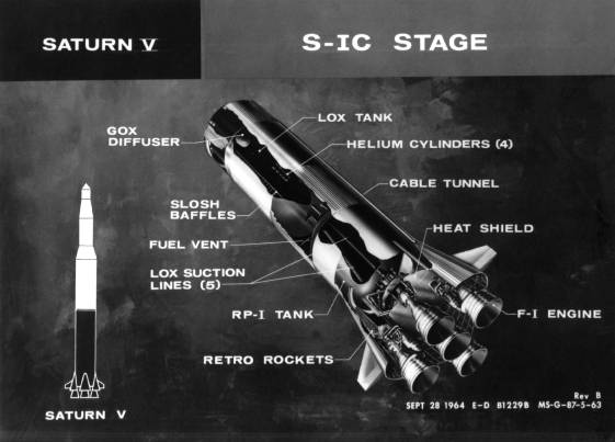
The components of Saturn V. (1) The first stage, S-IC. GOX stands for gaseous oxygen, LOX for liquid oxygen; RP-1 was a rocket propellant similar to kerosene.
Components of the AS-501's first stage (S-IC) were constructed by the Boeing Company at Michoud, Louisiana, and assembled at the Marshall Space Flight Center in Huntsville, Alabama. The S-IC stage consisted of a structural framework to which the engines were attached, an RP-1 (kerosene) fuel tank, a LOX (liquid oxygen) tank, an intertank structure separating the fuel and LOX tanks, and a forward skirt that connected to the second stage. The five Rocketdyne F-1 engines would develop a total of 33.4 million newtons (7,500,000 pounds of thrust) at liftoff. The center engine was fixed in position, but the others were mounted on gimbals to provide attitude control and steering for the vehicle. Two hydraulic actuators swiveled each engine in response to signals from the flight control computer located in the instrument unit. In less than 3 minutes of powered flight, the first stage engines would consume almost 2,000 metric tons of propellants. Eight small solid-propellant retrorockets were attached to the framework to slow the first stage after engine shutdown, guaranteeing separation of the first and second stages.
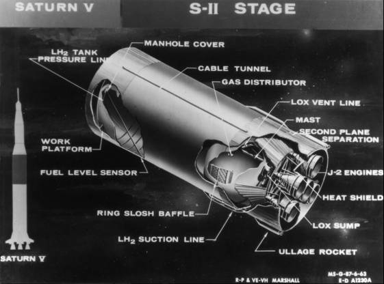
The components of Saturn V. (2) The second stage, S-II. LH2 means liquid hydrogen.
The second stage (S-II), built by North American Aviation, Inc., Canoga Park, California, consisted of an aft interstage, an aft skirt and framework to which the engines were attached, integral LOX and liquid hydrogen (LH2) tanks with a single common bulkhead, and a forward skirt. The five Rocketdyne J-2 engines were arranged similarly to those of the first stages, with the center engine fixed and the four outer engines gimbaled by hydraulic actuators in response to signals from the instrument unit. The aft interstage, which surrounded the rocket engines, was the means of attaching the second stage to the first stage; it also supported the weight of the second and third stages and the spacecraft. In flight when the first and second stages separated and the second stage engines ignited, the aft interstage was jettisoned. During the second stage's 6 minutes of powered flight, the five J-2 engines would consume about 425 metric tons of propellants while developing nearly 4.5 million newtons (one million pounds of thrust).
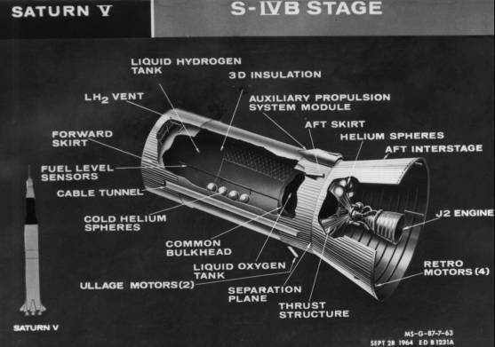
The components of Saturn V. (3) The third stage, S-IVB.
The third stage (S-IVB) of the launch vehicle was built by Douglas Aircraft Company. It consisted of the aft interstage, an aft skirt, a thrust structure to which the single J-2 engine was attached, a LOX tank and an LH2 tank, and a forward skirt. Because the third stage was smaller in diameter than the first and second stages, the aft interstage tapered from a diameter of 10 meters at its base to 6.6 meters where it joined the aft skirt. The single Rocketdyne J-2 engine would develop 889,600 newtons (200,000 pounds of thrust) and was capable of being shut down in space, and then reignited. Hydraulic actuators gimbaled the engine, in response to signals from the instrument unit, to provide pitch and yaw control during powered flight. Two self-contained auxiliary propulsion system modules, mounted 180 degrees apart on the aft skirt, would provide roll control during powered flight, and pitch, yaw, and roll control while the J-2 engine was shut down. During the approximately 7 1/2 minutes of third-stage powered flight (including first and second burns), about 105 metric tons of propellants would be consumed.
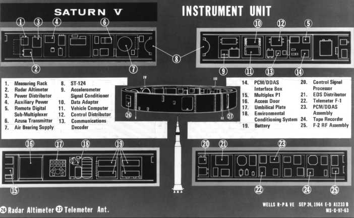
The components of Saturn V. (4) Schematic of the instrument unit, which was shaped like a ring or collar and placed around the upper end of the propellant tankage in what would otherwise have been wasted space.
IBM's instrument unit (S-IU), atop the third stage, was 6.6 meters in diameter, slightly less than one meter in height, and weighed about 10 metric tons. The unit consisted of segments of honeycomb material sandwiched between inner and outer skins and looked like a narrow collar or ring that had been slipped part way down the vehicle. Mounted on the inner skin were 16 cold plates, each 76 centimeters square. Coolant fluid circulated through these plates to dissipate heat generated by the operation of the guidance and control, instrumentation, and electrical power and distribution equipment installed on them. By attaching the equipment to the skin, space was left in the center for the domed bulkhead of the third-stage liquid-hydrogen tank, which extended into the instrument unit, and for the landing gear of the lunar module to be included on later missions.4
The flight plan called for the Saturn V to place the spacecraft and third stage into a circular orbit. After completing two orbits, the third stage would ignite a second time. Separating from the third stage, the spacecraft would rise to an apogee of approximately 18,500 kilometers by firing its service propulsion system engine. A second firing during descent from apogee would boost the command module's reentry velocity to 11,075 meters per second or 40,234 kilometers per hour. Protected by its heat shield, the command module would reenter the atmosphere and return to earth northwest of Hawaii.
| Next |