
Problems in Design
At Huntsville the Systems Support Equipment Laboratory designed the ground support equipment, a term applied to components used in the preparation, testing, monitoring, and launching of a rocket. The interface, or fit, of the launch vehicle and the support equipment largely determined the design of the latter. Accordingly, work in the Systems Support Equipment Laboratory paralleled Saturn development and was very much a research and design effort. Five design problems, in particular, challenged the laboratory: the launch pedestal, the hold-down and support mechanisms, the deflector, the cryogenic transfer equipment, and the umbilical tower.
Initial launch pedestal plans called for a hexagonal structure of tubular steel. George Walter, the laboratory's expert on structures, suggested a reinforced concrete design, which was eventually adopted. Walter's pedestal, 13 meters square and 8 meters high, was supported by corner columns and opened on all four sides to allow use of a two- or four-way flame deflector. A torus ring of large water nozzles, designed by Edwin Davis, encircled the 8-meter-wide exhaust opening. During launch and for some seconds thereafter, the nozzles would spray water on the pedestal, across the exhaust opening, and down the opening's walls, cooling the deflector and pedestal.9
A 1962 drawing showing the pad at LC-34, including the flame deflector, support arms, and hold-down arms.
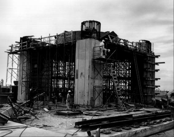
The pad under construction, 1960.
Designing the eight vehicle support arms to be located on top of the pedestal proved a long and difficult task. Four of the arms, cantilevered at the Saturn's outboard engines, would retract horizontally after ignition, providing clearance for the engine shrouds at liftoff. Should one of the engines fail during the first three seconds following ignition, these four arms could return to the support position. The possibility of damaging the rocket as it settled back on its supports complicated the design of the arms. The Systems Support team developed a nitrogen-fed pneumatic device that brought the support arms safely back under the launch vehicle within 0.16 second. The remaining four support arms were designed to hold the vehicle on the pad for three seconds after ignition so that blockhouse instruments could test engine thrust. Donald Buchanan's design section considered more than 20 different proposals before selecting one suggested by Georg von Tiesenhausen, Deputy Chief of the Mechanical Branch. Von Tiesenhausen's concept, modeled after an old German bottle top, had been planned for use in securing a Jupiter seaborne model.* The hold-down arms employed an over-center toggle device to achieve the necessary leverage and rapid release capability.10
The flame deflector design stirred debate within the laboratory: Should it have two or four sides? Should it be dry or wet (with cold water circulating through pipes beneath the metal shield)? The Huntsville engineers ruled out the four-sided deflector, previously used for Redstone and Jupiter missiles. The flame, spewing in all directions, would obstruct vision from the blockhouse and endanger equipment at the base of the umbilical tower. Both the size and cost of a wet deflector were unacceptable; one similar to those used on the test stands at Redstone Arsenal would cost ten times more than an uncooled deflector. Its size would increase the height of the launcher platform above ground, a dimension MFL wished to minimize. Despite doubts that a dry deflector could survive a single launch, a two-way uncooled deflector was selected.11
Fueling the Saturn promised to be another problem. The booster required 182,200 liters of liquid oxygen (LOX), six times the amount expended by the Jupiter missile. The LOX would evaporate at a rate of 163 liters every minute during fueling and up until launch; some provision for replenishing this loss was required. Explosive hazards dictated placement of the LOX facility a minimum of 200 meters from the launch vehicle. Orvil Sparkman, a Huntsville native who had been working on propellants since 1953, was responsible for designing the cryogenics equipment.
The main storage tank would be an insulated sphere with a diameter of 12.5 meters; it could hold 473,125 liters of liquid oxygen. A centrifugal pump would deliver the LOX through an uninsulated aluminum pipe to the filling mast on the launcher. This was the "fast fill" and operated at 9,460 liters per minute. With some of the LOX boiling off as its temperature rose during the filling process, a smaller (49,205-liter) tank would send additional LOX through a vacuum-jacketed line to replace the boil-off, thus keeping the vehicle tanks full. Since the launch team wanted to automate LC-34 fueling, remote controls were designed for the launch control center. Early plans called for a differential pressure sensing system in the rocket's LOX and RP-1 tanks to control propellant flow (much as a washing machine controls flow by measuring the difference in pressure between the top and bottom of the tank). At Debus's request, the system was later replaced by an electrical capacitance gauge. The LOX tank's fuel level sensor also actuated a pneumatic valve on the replenishing line.12
* In November 1955, Secretary of Defense Charles E. Wilson directed the Navy to adopt the Jupiter as a shipborne IRBM. Navy leaders, unenthusiastic about seagoing liquid-fueled rockets, subsequently were able to replace the Jupiter with the solid-propellant Polaris missile.
9. Davis interview; Walter interview, 21 Sept. 1973.
10. Von Tiesenhausen interview, 20 July 1973; Buchanan interview, 22 Sept. 1972.
11. Davis interview; Koelle, ed., Handbook of Astronautical Engineering, p. 28-44.
12. MSFC, C-1, C-2 Comparison, pp. 167-83; Wasileski interview, 14 Dec. 1972.
| Next |